Bus Channel Strips
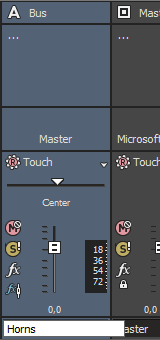
A separate channel strip is displayed for each bus in your project.
To show or hide channel strips for busses, click the Busses button in the View Controls pane.
Changing a bus's name
To rename a bus, double-click the label at the bottom of the channel strip and type a new name in the box (or press F2 to rename the selected bus). The channel strip in the Mixing Console is updated when you press Enter.

Adding or editing bus (insert) effects
When the Insert FX control region is visible, each bus displays its effects chain at the top of the channel strip.
To show or hide the Insert FX control region, click the Insert FX button in the View Controls pane.

Each effect is displayed as a button. You can hover over the button to see a ToolTip that displays the full plug-in and preset name.
TIP When the Insert FX control region isn't visible, you can click the Bus FX button  in the Faders control region to display the Audio Plug-In window for the bus effects chain.
Adding a plug-in
Click the  button and then choose a new plug-in from the menu to add a new plug-in to the effects chain.
Editing effects settings
Click an effect's button to display the Audio Plug-In window, where you can adjust the plug-in's settings.
When you right-click an effect's button, a shortcut a menu is displayed:
-
Choose Show <Plug-In Name> to open the Audio Plug-In window, where you can adjust the plug-in's controls.
-
Choose Bypass <Plug-In Name> to temporarily bypass a plug-in.
When an effect is bypassed, its button is displayed in red text.

-
Choose Remove <Plug-In Name> to remove a plug-in from the effects chain.
-
Choose Presets, and then choose a setting from the submenu to load a new preset. The current preset is indicated by a bullet (•).
-
To replace the current plug-in, right-click the effect's button, and then choose a new plug-in from the menu. Plug-ins are organized in submenus by type (EQ, Dynamics, Reverbs, etc.).
Adjusting bus send levels
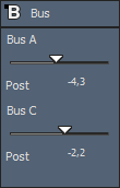
When the Sends control region is visible, each bus displays controls you can use to route the bus to assignable effects chains or to busses that are routed to hardware outputs. A bus cannot send to a bus that is directly or indirectly routed to the Master bus.
To show or hide the Sends control region, click the Sends button in the View Controls pane.

When the Automation Settings button  in the Faders control region is not selected, click the Channel Send button and choose a bus or assignable effects chain from the menu, and then drag the fader to adjust the send level.
When the Automation Settings button  in the Faders control region is selected, the fader handle is displayed as a
  , and you can use it to edit send volume automation on the bus track.
NOTE The trim level is added to the automation settings so your envelope is preserved, but with a boost or cut applied. For example, setting the trim control to -3 dB has the same effect as decreasing every envelope point by 3 dB.
TIP To adjust the size of the Sends control region, you can drag the bottom divider to make more or fewer sends visible.
Bus sends are post-volume (and post-mute) by default. To change to pre-volume (and pre-mute), click the Pre/Post button to switch to Pre-Volume Send mode.
Changing a bus's output device
When the I/O control region is visible, each bus displays controls you can use to set the bus's output device.
To show or hide the I/O control region, click the I/O button in the View Controls pane.

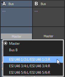
To choose an output device, click the Output button and choose a bus or hardware output from the menu.
IMPORTANT When you route busses to hardware outputs, the outputs from those busses will not be included in the mix when you render your project.
Monitoring bus levels with VU/PPM meters
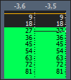
When the VU Meters control region is visible, you can display volume unit (VU) and peak program (PPM) meters to help you determine the perceived loudness of your audio signal (peak program meters provide faster response times to volume increases than VU meters).
To show or hide the VU Meters control region, click the VU Meters button in the View Controls pane.

Right-click the meter and choose a setting from the shortcut menu (or hover over the meter and roll your mouse wheel) to change the resolution and display options.
|
Item |
Description |
|
|---|---|---|
|
Show VU/PPM |
Use this command to show or hide meters for individual channels. |
|
|
Reset Clip |
Clears clipping indicators. |
|
|
Traditional VU |
The traditional VU meter is displayed with a scale of –10 dB to +2 dB. 0 dB on the VU meter equals 4 dBu. |
|
|
Extended VU |
The extended VU meter is displayed with a scale of –30 dB to +8 dB. 0 dB on the VU meter equals 4 dBu. |
|
|
Logarithmic VU |
Displays the meters in a logarithmic scale (like the Sound Forge peak meters) instead of the linear scales traditionally associated with VU meters. |
|
|
The UK peak program meter (also known as a BBC meter) is a Type II meter and is displayed with a scale of 1 to 7, which corresponds to a range of -12 to 12 dBu: |
||
|
UK Marks |
dBu |
|
|
7 |
12 |
|
|
6 |
8 |
|
|
5 |
4 |
|
|
4 |
0 |
|
|
3 |
4 |
|
|
2 |
8 |
|
|
1 |
-12 |
|
|
EBU PPM |
The EBU peak program meter is a Type II meter and is displayed with a scale of –12 to +12, which corresponds to -12 dBu to 12 dBu. 0 on the EBU PPM equals 0 dBu. The EBU PPM and UK PPM respond identically to increases in volume, but the EBU PPM decays more slowly. |
|
|
DIN PPM |
The DIN peak program meter is a Type I meter and is displayed with a scale of –50 dB to +5 dB, which corresponds to -44 dBu to 11 dBu. 0 dB on the DIN PPM equals 6 dBu. |
|
|
Nordic PPM |
The Nordic peak program meter is a Type I meter and is displayed with a scale of –42 dB to +12 dB, which corresponds to -42 dBu to 12 dBu. 0 dB on the Nordic PPM equals 0 dBu. |
|
|
Show Labels |
Toggles the meter level labels on and off. |
|
|
Show Peaks |
Toggles peak level indicators on the top of the meter. |
|
|
Hold Peaks |
When selected, the highest peak levels are represented by a thin line on the meter. |
|
|
Hold Valleys |
When selected, the lowest peak levels are represented by a thin line on the meter. |
|
|
Vintage Mode |
When Vintage Mode is selected, the VU meters use a different calculation method to simulate the response of analog VU meters. |
|
Monitoring bus levels with peak meters
When the Meters control region is visible, each bus displays meters you can use to monitor output levels.
To show or hide the Meters control region, click the Meters button in the View Controls pane.

NOTE If the Meters control region is not visible, peak meters are displayed in the Faders control region.
Right-click the meter and choose a setting from the shortcut menu (or hover over the meter and roll your mouse wheel) to change the resolution and display options.
TIP Right-click the peak meters and choose Show Peak Meter to show or hide meters for individual channels.
Muting or solo a bus
When the Faders control region is visible, each bus displays Mute  and Solo
  buttons.
To show or hide the Faders control region, click the Faders button in the View Controls pane.

Muting a bus
When the Automation Settings button  is not selected, you can click the Mute
  button to prevent a bus from being played in the mix. Click the Mute button on additional busses to add them to the mute group. To unmute a bus, click the Mute button again.
When the Automation Settings button  is selected, the Mute button is displayed as
  , and you can use the button to edit mute automation on the bus track.
Soloing a bus
Click the Solo button  to mute all unselected busses. Click the Solo button on additional busses to add them to the solo group. To remove a bus from the solo group, click its Solo button again.
Adjusting bus panning or volume
When the Faders control region is visible, each bus displays a Pan slider and a Volume fader.
TIP The Pan slider is displayed only when an input bus is routed to the master bus or an auxiliary bus. It is not available when the input bus is routed directly to a hardware output.
To show or hide the Faders control region, click the Faders button in the View Controls pane.

Adjusting panning
When the Automation Settings button  is not selected, you can drag the Pan slider to control the position of the bus in the stereo field: dragging to the left will place the bus in the left speaker more than the right, and dragging to the right will place the bus in the right speaker.
You can hold Ctrl while dragging the slider to adjust the setting in finer increments, or double-click the slider to return it to 0.
When the Automation Settings button  is selected, the Pan slider handle is displayed as a
  , and you can use it to edit pan automation on the bus track.
NOTE The trim level is added to the pan automation settings so your panning envelope is preserved, but with an offset applied. For example, setting the trim control to 9% left has the same effect as moving every envelope point 9% to the left.
Adjusting volume
When the Automation Settings button  is not selected, you can drag the Volume fader to control the overall (trim) volume of the bus.
You can hold Ctrl while dragging the slider to adjust the setting in finer increments, or double-click the slider to return it to 0.
When the Automation Settings button  is selected, the Volume fader handle is displayed as a
  , and you can use it to edit volume automation on the bus track.
NOTE The trim level is added to the volume automation settings so your envelope is preserved, but with a boost or cut applied. For example, setting the trim control to -3 dB has the same effect as decreasing every envelope point by 3 dB.
Changing pre/post routing
The Pre/Post-Fader Send button in the Sends control region and the Pre/Post Fader Insert FX button  in the Faders control region work together to determine the signal flow for your busses.
The Pre/Post Fader Insert FX button allows you to indicate whether the insert FX chain is affected by the channel's gain fader. When set to Post Fader Insert FX  , the FX chain is affected by the channel's gain. When set to Pre Fader Insert FX
  , the FX chain is not affected by the channel's gain fader, which is essential on the master bus when using plug-ins that dither the audio for final rendering.
The Pre/Post Fader Send button allows you to create cue mixes that are not affected by the gain (or mute/pan) stages of the bus or track. 
-
When Pre Fader Insert FX
 and Pre Fader Send are selected, your audio signal flows as follows: bus effects — bus send — bus pan — bus volume.
 -
When Pre Fader Insert FX
 and Post Fader Send are selected, your audio signal flows as follows: bus effects — bus pan — bus volume — bus send.
 -
When Post Fader Insert FX
 and Pre Fader Send are selected, your audio signal flows as follows: bus send — bus pan — bus volume — bus effects.
 -
When Post Fader Insert FX
 and Post Fader Send are selected, your audio signal flows as follows: bus pan — bus volume — bus effects — bus send.